倍福采用 XFC 技术的产品能够满足对快速控制、短响应时间以及微秒级确定性控制有极高要求的应用需求。该技术包含 EtherCAT 现场总线通信系统、高性能工业 PC、IP20 端子盒和 IP67 端子盒等 I/O 产品以及灵活的 TwinCAT 自动化软件。
XFC 技术具有更高的时间分辨率,为精度要求极为严苛的工艺流程带来了显著的优势。得益于优化的控制架构和各种子技术的集成,系统响应时间可远低于 100 微秒。因此,即使采用标准模块,也能以高精度和高可靠性实现高动态的离散控制场景。
XFC 技术包含以下来自不同产品领域的子技术:分布式时钟、时间戳/多时间戳、超采样、亚微秒级高速输入和输出以及微增量。这些子技术对于确保 XFC 系统的高性能和高精度起着关键作用。
XFC 技术详解

分布式时钟
分布式时钟可为所有总线设备创建统一的时间基准,这对于实时过程来说至关重要,并能实现不同模块事件的精准同步。这样可以将控制动作与控制/总线周期解耦,使其可在时间轴上自由移动。分布式时钟可以实现时间确定的信号采集和输出,显著提升了工业应用的性能与可靠性。凭借其统一的时间基准,分布式时钟为所有其它 XFC 技术提供了基础支撑。
- CPU、I/O 和驱动设备的分布式绝对系统时间同步
- 内部时间分辨率:10 ns
- 分布式时钟精度:<<1 µs
- 与其它时间系统同步(外部同步功能)

时间戳
时间戳/多时间戳支持将统一分布式时钟系统时间作为数据类型进行处理。该技术能够实时精确记录事件发生的时间戳。时间戳使得数字量和模拟量事件的记录以及输出设置都可独立于总线周期。例如,这样能够实现多个驱动轴之间以及与系统时间之间的精确同步。与单个时间戳不同,多时间戳允许在每个 PLC 周期内处理多个开关量结果。
- 时间戳
- 数字量信号单次事件触发的时间测量非常精确:分辨率为 1 ns,内部采样分辨率在 ns 范围内
- 分布式时钟绝对时间的分辨率为 64 位,可以实现轻松的时间处理 > 580 年
- 多时间戳
- 每个周期可以实现 32 个事件的精确时间测量:分辨率为 1 ns,内部采样分辨率在微秒范围内
- 时间分辨率为 32 位的分布式时钟,足够用于完成 ±4 秒时帧内的动作

超采样
超采样技术可在不改变 PLC 周期的情况下,在设备端实现更高的采样速率。该技术通过在总线周期内以等时间间隔进行多次采样,并将测量数据打包传输。与标准评估方式(每个总线/控制周期 1 次测量)相比,高采样频率能够以更优的时间分辨率捕获信号,并可采集更高频率的信号。此类信号的传统检测方法需要缩短周期时间,但这会受到控制系统实际条件的限制。而超采样输出则可实现比周期时间更高的控制频率,从而在每个总线/控制周期内发出多个控制指令。
- 支持模拟量 I/O EtherCAT 端子模块(截至 2024 年):信号转换速率最高可达 100 kSps/10 µs
- 支持 EtherCAT 数字量 I/O 端子模块(截至 2024 年):最高 10 MSps/100 ns
- 支持角度/位移测量(截至 2024 年):最高 100 ksps/10 µs
快速响应
如果采用输入/输出延迟极低(<1微秒)的 I/O 设备,总线信号可直接转换为物理输出信号,反之亦然。再结合其它 XFC 技术,就能通过倍福标准组件实现最快的信号处理。若配合基于 EtherCAT 的高速现场总线通信以及倍福高性能工业 PC 的短控制周期,可以实现极短的响应时间。
- 通过中央控制器可实现控制回路延迟时间 < 50 µs
- 输入/输出信号的确定性同步转换可以减少处理时间抖动
- 处理时间抖动独立于通信和 CPU 抖动

微增量
在评估轴位置/编码器时,微增量通过基于时间插值的方式在编码器实际增量之间生成额外增量,从而提高编码器计数值的空间分辨率。系统通过内部测量当前速度并据此对微增量进行插值计算。这使得编码器数值更接近轴的真实位置。
- 插值分辨率为 8 位
- 通过分布式时钟持续周期性地测定编码器计数值
XFC 应用
超采样和时间戳功能助力实现高频激光控制器
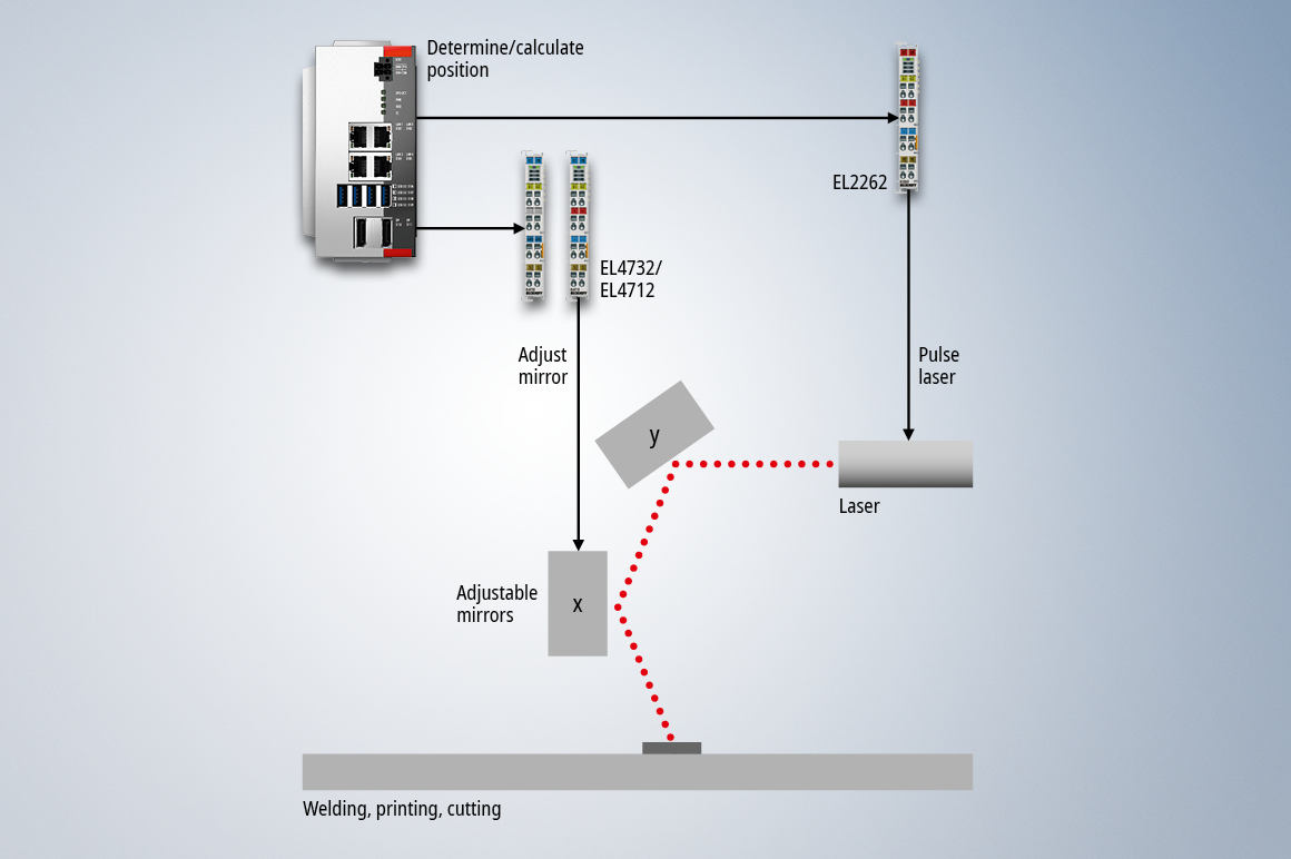
激光技术广泛应用于各种需要高精度和高速度的工艺过程。为确保性能,许多应用场景中都会采用 XFC 技术控制激光,通过分布式时钟将激光触发时间与光束校准进行同步。高更新速率是实现光束快速精准引导的关键。
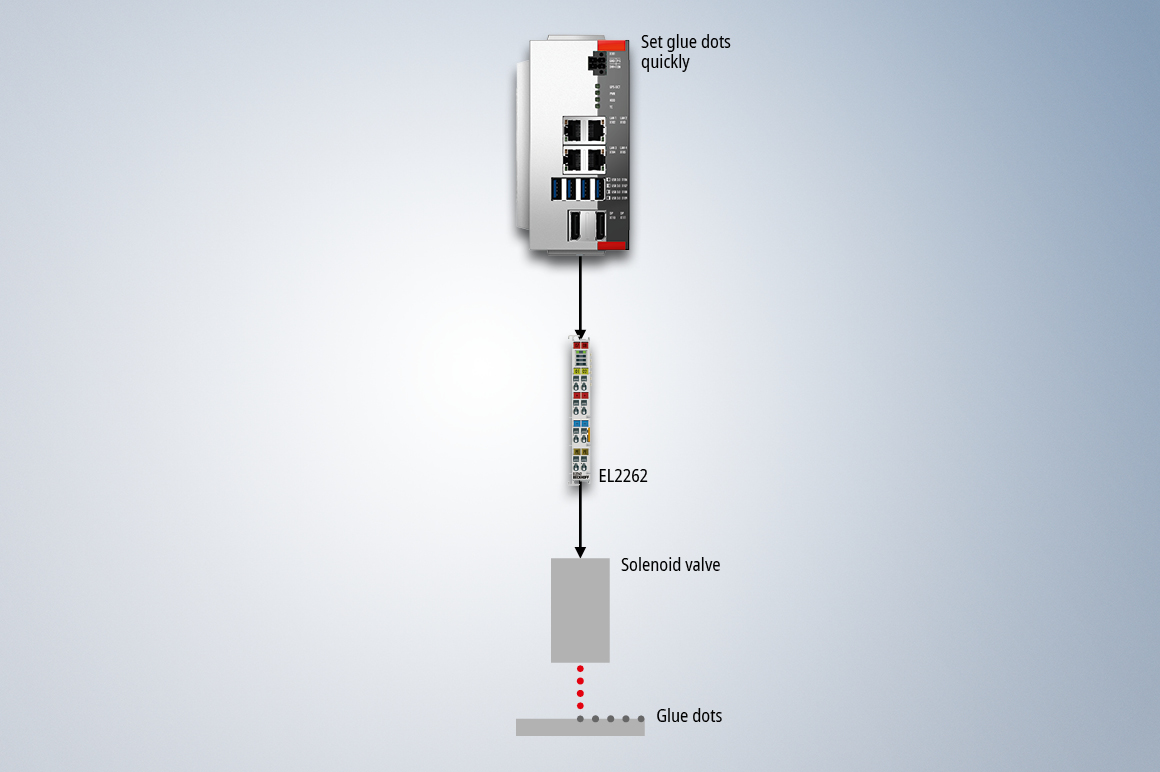
为此,系统采用了具备超采样功能的 EL2262 数字量输出端子模块,它可实现时间间隔为 10 µs 的高速激光启停控制。激光束的校准通过两个电动可调反射镜实现,这两个反射镜分别负责 X 轴与 Y 轴 方向的定位。借助 EL4712 或 EL4732 输出的模拟量超采样电流信号,反射镜定位可保持与激光相同的高更新速率, 确保激光器在启停瞬间能够毫无延迟地从一个位置切换到下一个目标位置。
时间戳/多时间戳功能助力实现相机控制
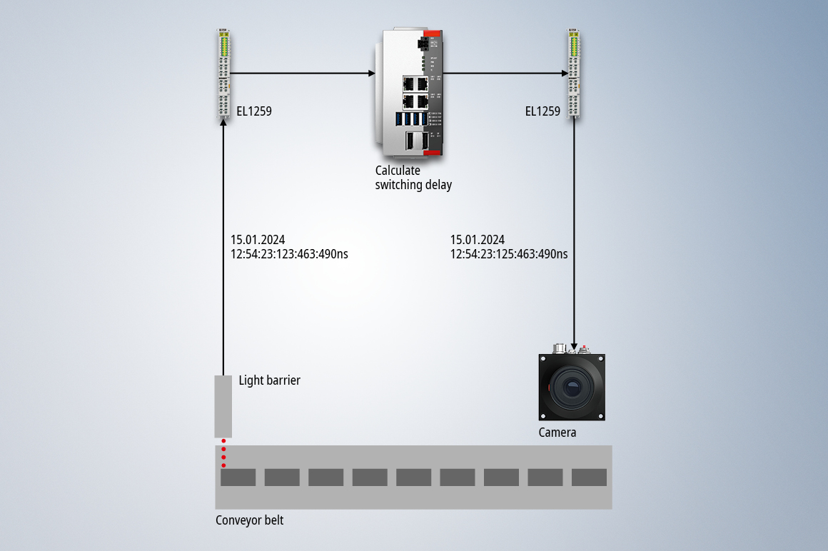
在各种生产流程的视觉检测中,需要精准触发相机系统。例如,相机必须与传送带的运动同步触发。这种时序精度对于图像处理效果至关重要,但在传统自动化系统中却无法自由选择该精度 — 受限于总线周期在毫秒级时间框架内对输出信号切换时机的决定。
借助 XFC 时间戳技术,系统可首先通过微秒级精度的数字量输入端子模块确定传送带上待成像物体的位置,然后通过数字量时间戳输出端子模块在精准时刻触发相机 — 整个过程独立于系统周期。
超采样测量端子模块和分布式时钟助力实现高效结构监测
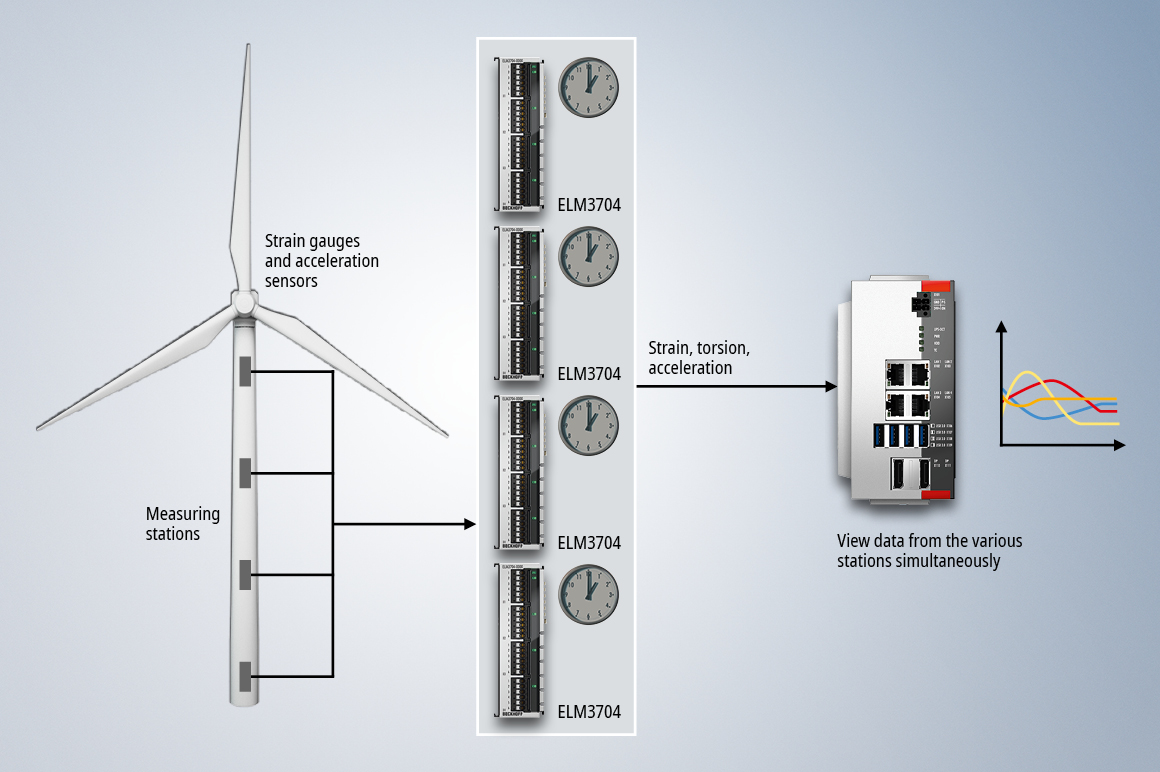
在对风力发电机组等结构进行健康监测时,需在多个不同位置同步采集大量数据。以风力发电机组为例,整个风机机身通常会分布多个采用不同测量技术的监测点。通过关联分析各监测点的数据,可准确评估整个系统的结构完整性。
为了对所有测量值进行相互比较,测量端子模块需要基于统一的时基来采集这些数据。分布式时钟技术用于提供这一统一的时基。这意味着,即使是通过超采样技术高频采样到的测量值,也能被纳入结构监测系统。
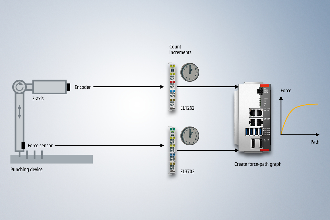
同步超采样测量技术助力生成冲压工艺中使用的力-位移曲线图
力曲线的记录对于某些工序的监测至关重要。如果要将力曲线与冲床位置显示在功能曲线中,则需要确保各测量值之间的时间同步性。
这种同步性通过分布式时钟的统一时基实现。此外,力传感器与增量编码器的数据采样速率分析必须保持一致。超采样技术确保在高速冲压过程中,仍能高精度采集力-位移曲线数据。
应用报告
-
 应用报告
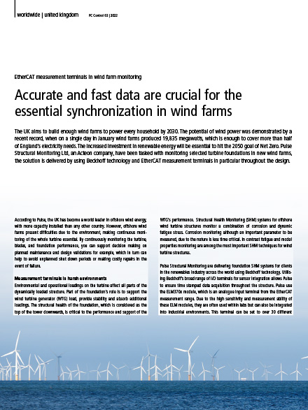
应用报告高速、高精度的数据传输是实现风电场的同步的关键
Pulse, 英国
英国推出“2030 年全民风电”计划,即到 2030 年用海上风电为全英所有家庭供电。根据英国的电网数据显示,一月份某一天风电场的发电量达到了 19,835 兆瓦,足以满足英格兰一半以上的供电需求,充分证明了风力发电的巨大潜力。加大可再生能源的投资力度对全球实现 2050 年“净零排放”目标至关重要。Acteon 集团旗下的 Pulse Structural Monitoring 公司受委托为新风电场中所选的风机基础提供监测解决方案,整个解决方案,尤其是在整个设计过程中,使用了大量倍福基于 PC 的控制产品和 EtherCAT 测量端子模块。
-
 应用报告
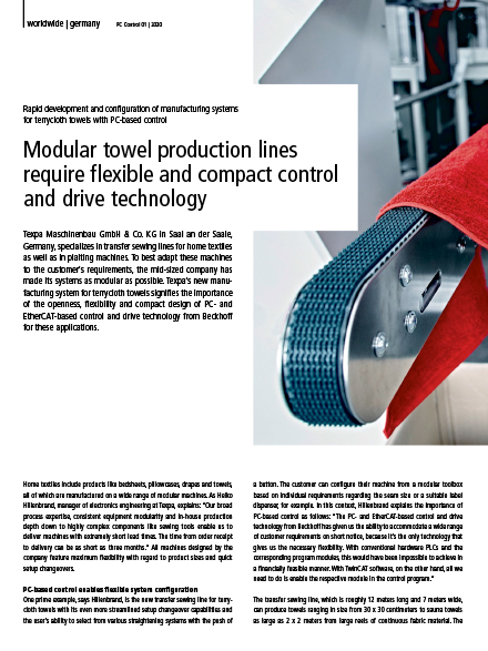
应用报告模块化毛巾生产线需要灵活、紧凑的控制和驱动技术
Texpa, 德国
德国泰克斯帕(TEXPA)机械有限公司位于德国萨尔州萨尔市,是全球领先的家用纺织品自动化缝纫设备制造商。为了让这些设备能够更好地满足客户需求,这家中型公司已使其系统尽可能地模块化。Texpa 公司的新型毛圈毛巾生产系统很好地说明了倍福基于PC 和 EtherCAT 的控制和驱动技术的开放性、灵活性和紧凑设计对于这些应用的重要性。
-
 应用报告
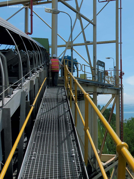
应用报告大陆集团:高速、高精度测量技术能够早期检测出输送带损伤
Continental Engineering Services GmbH, 德国
ContiTech 和 Continental Engineering Service 公司共同开发了两套输送带监测系统。这两套系统需要非常快速、高精度地记录和处理传感器数据。倍福的 EtherCAT 和 XFC 极速控制技术提供了一个高效的解决方案。
-
 应用报告
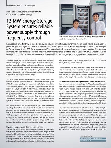
应用报告High-precision frequency measurement with eXtreme Fast Control technology in a 12 MW energy storage system
POWER21 Corp., 韩国
In order to protect against grid fluctuations, Korean engineering firm, Power21 has developed an Energy Storage System (ESS) for frequency control. EL3773 EtherCAT Terminals with eXtreme Fast Control (XFC) technology perform high-precision frequency measurements.
-
 应用报告
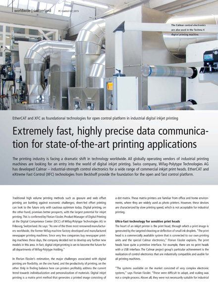
应用报告超高速、高精度数据通讯用于最先进的印刷应用
WIFAG-Polytype Holding AG, 瑞士
印刷业正面临着全球范围内的技术巨变挑战。全球所有工业印刷机运营商正在寻求一个进入数码喷墨印刷领域的契机。瑞士 Wifag-Polytype Technologies 公司成功开发了 Calmar — 用于各种商用喷墨打印头的工业级控制电子设备。Beckhoff 的 EtherCAT 和 XFC 极速控制技术为开放式高速控制平台提供了坚实的基础。
-
 应用报告
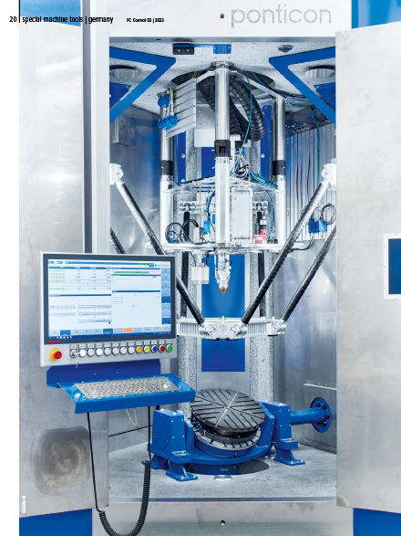
应用报告高速高精度的软件协调控制
Ponticon GmbH, 德国
如今,激光熔覆技术通常用于涂装旋转对称部件。总部位于德国威斯巴登的 Ponticon 公司借助 pE3D 系统将应用范围扩展到任何几何形状的涂层和快速成型制造。如果没有倍福的 TwinCAT CNC、EtherCAT 和 XFC 极速控制技术,就很难实现对三脚架、旋转/摆动工作台和激光的精确控制和协调。
-
 应用报告
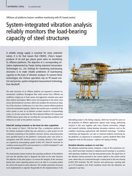
应用报告系统集成振动分析助力可靠监测钢结构的承载能力
天津奥菱 中国海油, 中国
可靠的能源供应对于每个工业国家来说都至关重要。因此,中国海洋石油集团有限公司(简称“中国海油”或“中海油”)— 中国最大的海上油气生产商,非常重视海洋平台的监测工作。天津奥菱工业自动化科技有限公司(以下简称奥菱)受中海油委托,实施了支撑结构监测解决方案,旨在基于振动分析对承载能力进行可靠预测。他们采用倍福基于 PC 的控制技术和系统集成式高精度测量产品,以实现所有这些技术设备的互联互通。
-
 应用报告
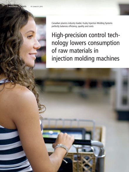
应用报告高精度控制技术帮助减少注塑机的原材料浪费
赫斯基注塑系统有限公司, 加拿大
PET 塑料瓶全球市场的巨大份额都取决于使用加拿大塑料行业创新者赫斯基注塑系统有限公司的机器生产的瓶坯。
-
 应用报告
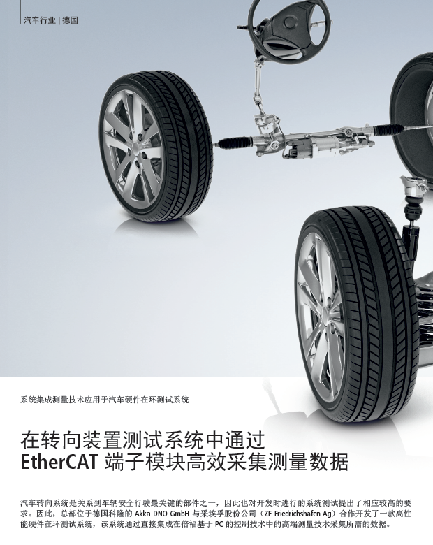
应用报告在转向装置测试系统中通过 EtherCAT 端子模块高效采集测量数据
Akka DNO GmbH und ZF Friedrichshafen AG, 德国
汽车转向系统是关系到车辆安全行驶最关键的部件之一,因此也对开发时进行的系统测试提出了相应较高的要求。因此,总部位于德国科隆的 Akka DNO GmbH 与采埃孚股份公司(ZF Friedrichshafen Ag)合作开发了一款高性能硬件在环测试系统,该系统通过直接集成在倍福基于 PC 的控制技术中的高端测量技术采集所需的数据。


